Full reference: Bodóczi A., Pintye B., Kciuk M. (2025). Precise laser scanning for floor flatness: Methodology and applications for surveying, registration, and analytics.’. (In Press)
Abstract
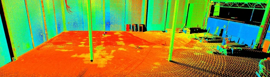
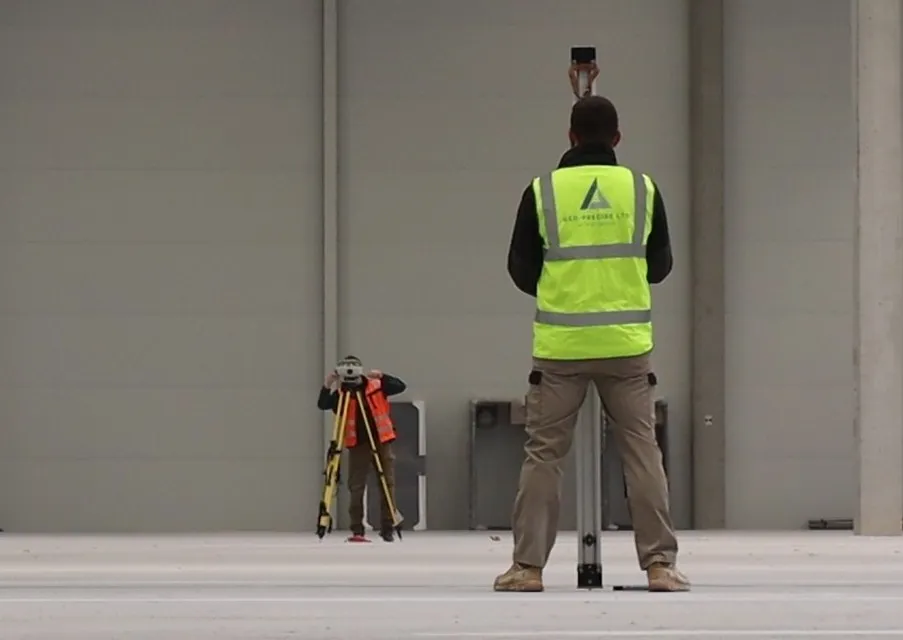
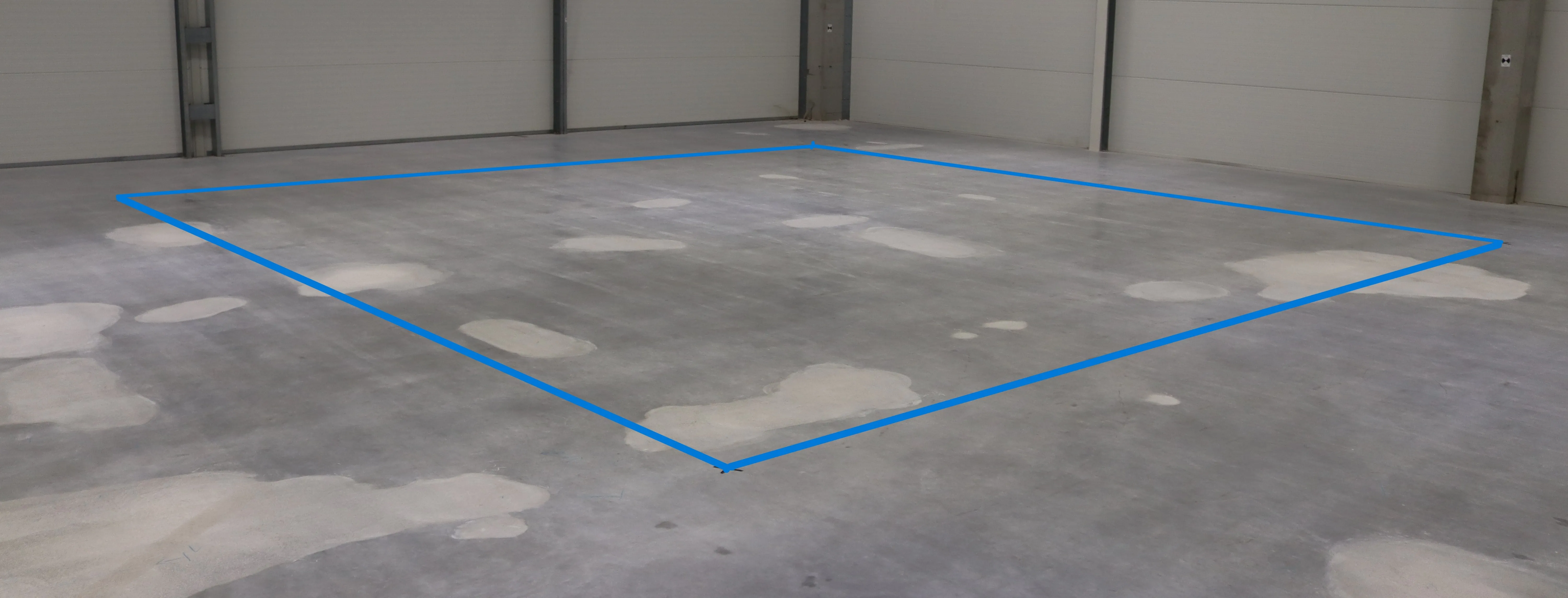 Figure1: Test slab
This study investigates the application of Terrestrial Laser Scanning (TLS) for high-precision floor flatness assessment in survey engineering. The objective was to evaluate the vertical accuracy of a laser scanner against reference data from precise levelling, using industry standards to calculate the Test Uncertainty Ratio (TUR). A controlled indoor floor surface was surveyed by setting out a grid with a total station and measuring elevations at each intersection with a digital level. The same area was scanned, and TLS-derived elevations were extracted for comparison. Results showed that over 98% of values fell within ±0.5 mm of the reference, with a standard deviation of 0.2 mm. TLS also reduced total survey and processing time by two-thirds. These findings demonstrate the high vertical accuracy and efficiency of TLS, supporting its integration into routine quality control workflows for floor construction and similar precision surveying applications.
1. Introduction and Background
Flatness control plays a critical role in the functional and structural performance of industrial concrete floors. Surface Regularity (SR), defined as the deviation in height of the surface over short distances in a local area [2], must be evaluated with precision to ensure compliance with construction tolerances, especially in high-performance facilities such as robotic warehouses. Traditional straightedge method - despite its simplicity and cost-effectiveness - became obsolete in the 21st century due to its low positional precision, limited repeatability, and labour-intensive application over large areas [2]. Studies highlight that it is inexact and rarely representative of the entire floor due to operator subjectivity and limited coverage.
To address these limitations, the F-Number system was developed and introduced in the 1970’s. This involves defining a grid of floor profile survey lines, measuring point elevations at regular intervals, and calculating flatness and levelness values to summarize the floor profile. However, this method still relies on discrete, contact-based tools such as optical levels or rolling profilers, requiring considerable time and offering limited spatial details [2][4] . These manual surveying methods can require between 2 and 12 hours to complete a single slab, depending on its size, and the placement of profile lines is still determined arbitrarily.
In contrast, TLS enables broad, non-contact surface measurements at high-resolution. It can acquire dense measurements for entire surfaces [1], collecting millions of 3D points every second.
Previous researchers have reported accuracies of 0.5 mm when using TLS for surface geometry assessment [1][3] and noted significant advantages in both time and completeness compared to manual methods [4] . However, despite its growing use in construction, rigorous validation of TLS performance for floor flatness - especially against conventional levelling - remains limited.
This study addresses that gap by validating the results of TLS against a precisely levelled grid on a controlled indoor floor. In addition to assessing statistical accuracy and uncertainty, a practical time-efficiency comparison was carried out to quantify workflow improvements.
2. Methodology
The test surface consisted of a 9.9 × 9.9 m concrete slab located within a robotic warehouse. The area was chosen to simulate a standard scan layout used in large-scale floor scanning projects, where setups typically following a grid pattern. A 300 mm grid of points were marked on the slab using a Leica TS16 total station (Figure 1, 2). Elevation values were measured at all 1156 grid intersections using a Leica LS15 digital level and an invar barcode staff.
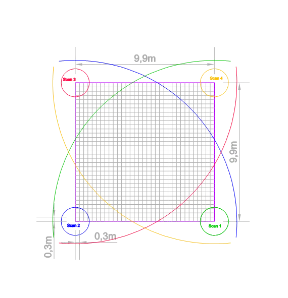
Figure 2: Grid layout, dimensions of survey area and scan positions
To validate the reliability of the control grid, a levelling check was conducted by repeating four evenly distributed runs across the same grid of points. A total of 136 paired readings were analysed, yielding a standard deviation of 0.07 mm between the original and check values - indicating high internal consistency within the levelling dataset.
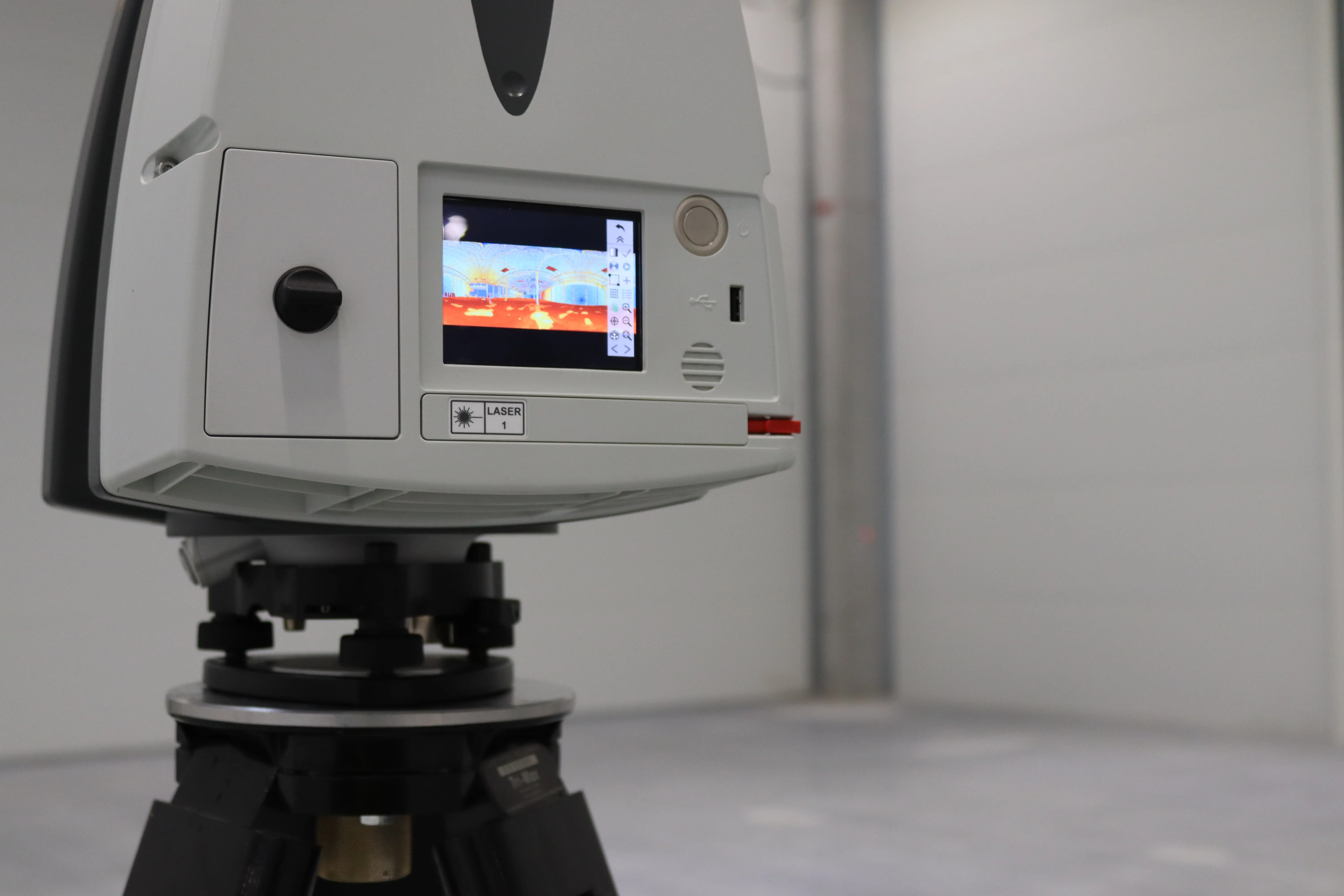
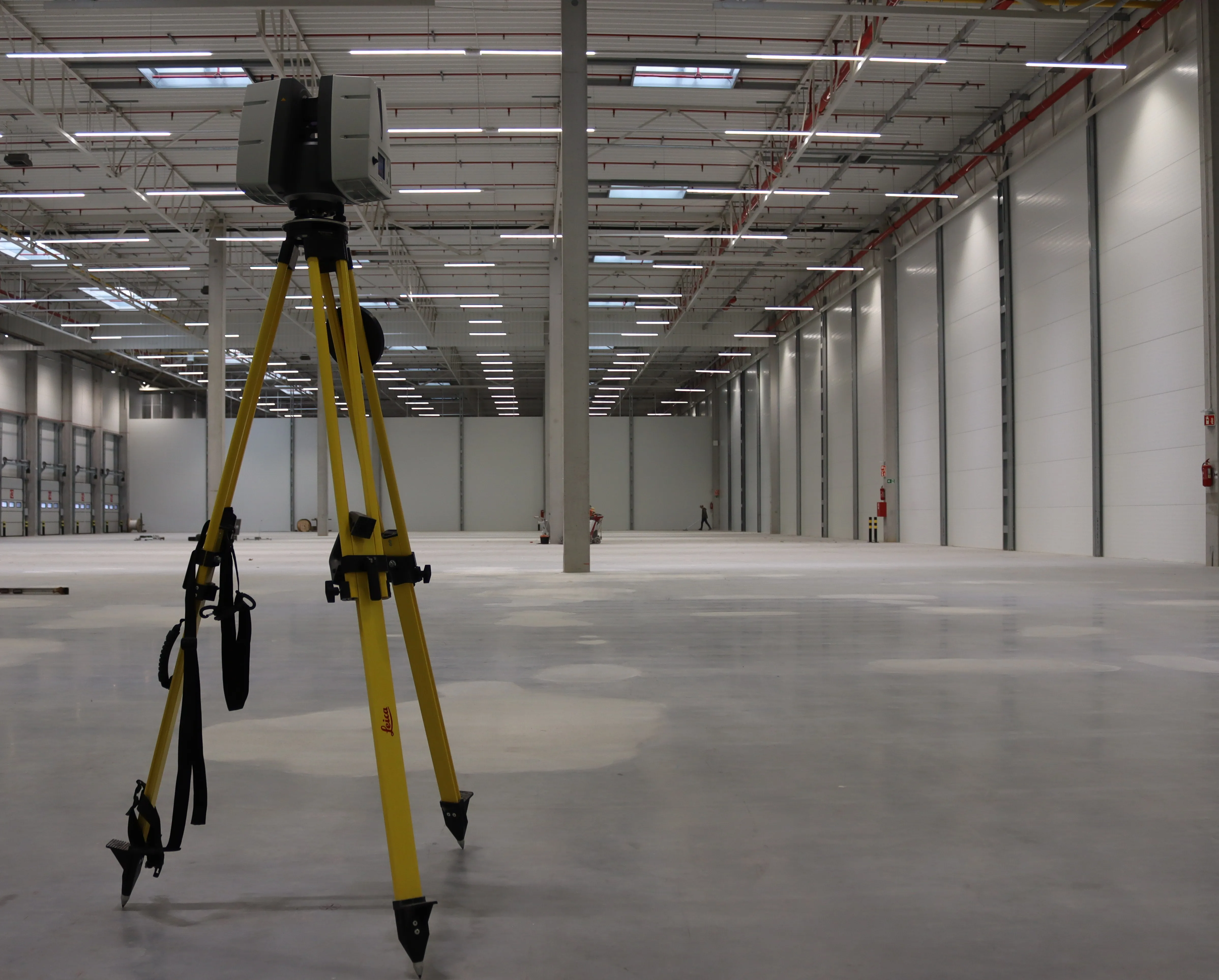
Two independent TLS surveys were then performed using a Leica P40 laser scanner. Each scan set comprised four scanning positions arranged near the grid corners, each approximately 2 m in height and spaced no more than 10 m apart. The scans were conducted with a 6 mm × 6 mm resolution at 10 m distance. In both datasets, black-and-white targets were recorded to support coordinate referencing, although cloud-to-cloud registration remained the primary alignment method as this provides effective means of maintaining relative accuracy across large continuous areas.
3. Results and Analysis
3.1 Comparison to Base Survey
To compare the base survey data with the laser scan-derived elevations, FLAT4’s Ground Control function was employed. FLAT4 is a software solution for surface geometry analysis by Even Horizon Ltd. It uses algorithmic geometry to calculate and compare the relation of the points of a digital surface model and to produce SR reports and grinding plans [5]. Ground Control function, developed for verifying the vertical accuracy of point clouds prior to SR calculations, was ideally suited for the task.
The results of this comparison for both scan sets are summarised below:
|
Scan 1 |
Scan 2 |
|
|
Mean Deviation (μ) |
0.06 mm |
0.09 mm |
|
Standard Deviation (σ) |
0.186 mm |
0.195 mm |
|
Std. Uncertainty of Mean |
0.00547 mm |
0.00574 mm |
|
% < ±0.5 mm |
98.18% |
98.88% |
|
% < ±0.3 mm |
89.53% |
89.99% |
|
% < ±0.1 mm |
44.55% |
40.05% |
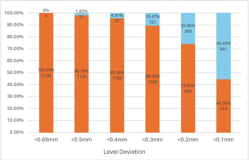
Figure 3: Distribution of deviation between base readings and Scan 1 data
Another, scan-to-scan comparison showed a mean difference of 0.2 mm with a standard deviation of 0.148 mm, confirming repeatability.
These results align with previous studies, which showed that TLS can provide data with sufficient accuracy to conduct standard surface regularity control and that the technology compares favorably with the traditional manual measurement approach [1].
3.2 Accuracy and Uncertainty Evaluation
Measurement reliability was evaluated using the Test Uncertainty Ratio (TUR) method, following ANSI/NCSL Z540.3-2006. Assuming a floor flatness tolerance of 3.0 mm - typical for DIN 18202 (Table 3 Line 4) and ASTM F50 - the calculated TUR values were:
Scan 1 TUR: 3.0 mm / (2 × 0.186 mm) = 8.1 : 1
Scan 2 TUR: 3.0 mm / (2 × 0.195 mm) = 7.7 : 1
Both results exceed the 4 : 1 threshold required for reliable performance, and even the minimum tolerances needed to meet this threshold - 1.49 mm and 1.56 mm - fall below the limits of the most stringent floor standards, such as TR34 FM1 (1.8 mm) and ASTM F100 (1.59 mm).
4. Efficiency Evaluation
Beyond precision, TLS offers considerable advantages in speed and labour. A time study compared the total hours spent conducting the levelling survey and TLS-based workflow, from field data collection to final processing (Figure 4).
|
Task |
Levelling |
TLS |
| Site Time | 29.00 hrs | 1.00 hrs |
| Processing Time | 2.25 hrs | 8.00 hrs |
|
Total |
31.25 hrs |
9.00 hrs |
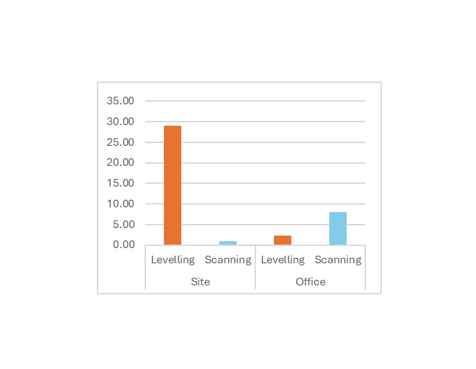
Figure 4: Working hours spent on and off site
The TLS-based method required less than third the total time of the traditional workflow, with 29 times faster site work in this particular case. This efficiency aligns with earlier findings that TLS allows a large amount of deviation measurements in negligible times and provides more complete, hence more reliable flatness control results [1][4] . The ability to quickly collect dense data and automate analysis reduces field exposure and subjectivity making TLS especially suitable for large-scale or time-sensitive floor projects.
5. Conclusion
This study confirms that TLS is a viable and highly effective alternative to traditional methods for floor flatness verification. Across two independent scan sets, the Leica P40 scanner demonstrated sub-millimetric accuracy, with over 98% of deviations falling within ±0.5 mm of the control data and SD below 0.2 mm. Test Uncertainty Ratios exceeded 7.7:1 in both cases confirming compliance with leading flatness standards.
The significant time savings observed - even 20 times faster site work - further establish TLS as a compelling solution for floor surveying applications. When applied using a consistent, quality-controlled workflow, TLS provides a repeatable, standards-compliant, and efficient methodology for high-performance floor construction and verification.
6. Acknowledgements
The research was made possible through the collaboration of GEO-PRECISE Ltd, Mat-Map Survey Ltd. (civil engineering), Fibre System Sp. z o.o. (industrial floor construction) and Even Horizon Ltd. (tech engineering) who contributed technical expertise, equipment, software, and testing facilities. Special thanks are extended to Leica Geosystems Hungary Kft and Dr. Zoltán Koppányi for their constructive comments, which significantly contributed to the clarity and quality of this work.
7. References
[1] – Bosché, F & Guenet, E 2014, ‘Automating surface flatness control using terrestrial laser scanning and building information models’, Automation in Construction, vol. 44, pp. 212-226.
[2] – Bosché, F & Biotteau, B 2015, ‘Terrestrial laser scanning and continuous wavelet transform for controlling surface flatness in construction - a first investigation’, Advanced Engineering I formatics, vol. 29, no. 3, pp. 591-601.
[3] – Tan, Y.; Liu, X.; Jin, S.; Wang, Q.; Wang, D.; Xie, X. A Terrestrial Laser Scanning-Based Method for Indoor Geometric Quality Measurement. Remote Sens. 2024, 16, 59.
[4] – Xu, C., Xiong, W., Tang, P., & Cai, C. S. (2024). Automated flatness assessment for large quantities of full-scale precast beams using laser scanning. Computer-Aided Civil and Infra-structure Engineering, 39, 1868–1885. https://doi.org/10.1111/mice.13162
[5] Flat4 - https://flat4.evenhorizon.co.uk/